The user can set-up, analyze and view the results of a model using the following 12 simple steps:
A. Pre-Processing: Building the Model
1. Click ![]() to define the System of Units. This is a very important step for the model. For details, see Units
to define the System of Units. This is a very important step for the model. For details, see Units
2. Click ![]() to define Material(s). You need to define the Material Name (optional), Elastic Modulus E, Density d (optional) and Yield Stress fy (optional) for each Material. For details, see Materials.
to define Material(s). You need to define the Material Name (optional), Elastic Modulus E, Density d (optional) and Yield Stress fy (optional) for each Material. For details, see Materials.
3. Click ![]() to define Sections(s). You need to define the Section Name (optional), Area A and Moment of Inertia I (optional) for each Section. For details, see Sections.
to define Sections(s). You need to define the Section Name (optional), Area A and Moment of Inertia I (optional) for each Section. For details, see Sections.
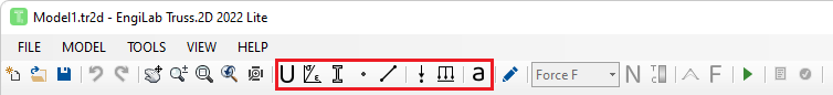
4. After you have defined at least one Material and one Section, you can start drawing your Model on screen, as follows:
•Left-click on screen to define a new free Node (with no constraints).
•Left-click on screen, hold down the left button and then release it at another location to define a new Element and two nodes at ends i, j.
•Double-click on a Node or close to it to to define a new Constraint (Support) set. Each time you double-click a Node, a new Nodal Constraint set is applied to the Node.
•If SNAP is activated (Default=True), then you can only draw Nodes and Elements at increments defined by the Snap Size setting (Default=0.1).
•If SNAPNODE is activated (Default=True), then you can "catch" Nodes so that new elements can be connected to existing Nodes.
•Note: All Elements that are defined on screen are assigned the Default Material and the Default Section. The Default Material and Section can be selected in the Materials and Sections forms, respectively.
If you do not want to use on-screen drawing, you can still click ![]() to define Nodes manually and
to define Nodes manually and ![]() to define Elements manually.
to define Elements manually.
5. Click ![]() to:
to:
•Move existing Nodes to their exact positions, if needed. For example, a Node with X-Coordinate 5.8 is defined on screen with Snap Size = 0.1, but it should be moved to the exact position 5.85.
•Define or change Nodal Constraints (supports).
•Define Springs.
•Use tools related to Nodes, such as the Move Nodes tool, Copy Nodes tool, and others.
For details, see Nodes.
6. Click ![]() to:
to:
•Assign the right Material and Section to every Element, if needed. All Elements that are defined on screen are assigned the Default Material and the Default Section, but the user can change this later on, if needed.
•See properties of Elements such as Length, and others.
For details, see Elements.
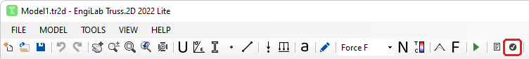
7. Click ![]() to define Nodal Loads. For details, see Nodal Loads.
to define Nodal Loads. For details, see Nodal Loads.
8. Click ![]() to define Elemental Loads. For details, see Elemental Loads.
to define Elemental Loads. For details, see Elemental Loads.
9. Click ![]() to define Body (Acceleration) Loads (if needed), for example to take into account the self weight of the structure. For details, see Body (Acceleration) Loads.
to define Body (Acceleration) Loads (if needed), for example to take into account the self weight of the structure. For details, see Body (Acceleration) Loads.
•If you want to take into account the self-weight of Elements as an additional uniform load for each Element, then you have to provide the Material Density for the Material of each Element and also to define a Linear Acceleration Vector equal to the standard earth gravitational acceleration. A common practice is to set the earth gravitational acceleration with a minus (-) sign at the Y direction - this means gravity acting towards -Y global axis.
•Example:
Using Consistent Units, if you are using kN for forces, m for length and s for time, then the Material Density has to be given in t/m3 and you have to enter -9.80665 (or simply -9.81) at the aY component of the Linear Acceleration Vector.
Using another System of Units, you simply have to enter the value of the standard earth gravitational acceleration in this system (check the Acceleration unit used in Units).
B. Analyze the Model
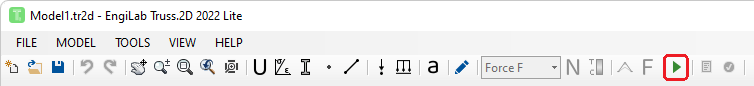
10. Click ![]() (or press F5) to run the Finite Element Analysis. For details on the Analysis, see Analysis.
(or press F5) to run the Finite Element Analysis. For details on the Analysis, see Analysis.
C. Post-Processing: See the Analysis Results
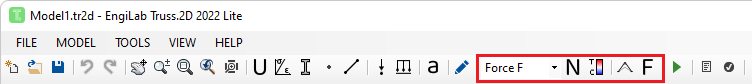
11. Click ![]() ,
, ![]() ,
, ![]() or
or ![]() to see the Axial Diagrams, Color Plots, Model Deformation or the Free Body Diagram, respectively.
to see the Axial Diagrams, Color Plots, Model Deformation or the Free Body Diagram, respectively.
•![]() : Axial Diagrams for Force, Stress or Strain
: Axial Diagrams for Force, Stress or Strain
•![]() : Color Plots for Force, Stress or Strain
: Color Plots for Force, Stress or Strain
•![]() : Deformation (deformed shape of the Model)
: Deformation (deformed shape of the Model)
•![]() : Free Body Diagram (external forces together with the support reactions)
: Free Body Diagram (external forces together with the support reactions)
12. Click ![]() to see the analytical results.
to see the analytical results.
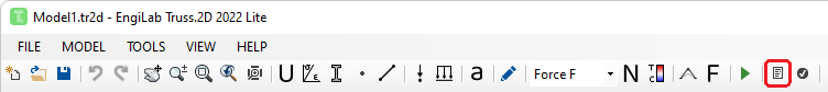
The analytical results include:
D. Analysis Validation (optional)
Optionally, you can click ![]() to see the Analysis Validation Reports and make sure that everything is OK with the Analysis and its results.
to see the Analysis Validation Reports and make sure that everything is OK with the Analysis and its results.