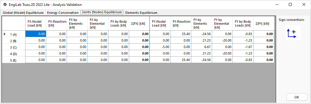
This tab shows the calculations related to the Equilibrium of Joints (Nodes). After the Analysis, every joint of the 2D Truss needs to be in equilibrium state, i.e. the Sum of X-Forces and the Sum of Y-Forces need to be all zero for every joint of the Model. The program calculates all the Forces on each joint and also the Sums Σ(FX) and Σ(FY), as shown below.

For this calculation, the following forces are taken into account for each direction, X and Y:
1.Any Nodal Force on the joint, i.e. the external Nodal Load. See the 1st column for the X- and Y-directions in the figure above.
2.Any Support Reaction Forces from any constraints (supports) or springs on the Node. See the 2nd column for the X- and Y-directions.
3.The Forces contributed by Elements that are "connected" to the Node. An Element with a tensile force F connected to a Node is "pulling" the Node with this Force along its direction. Similarly, an Element with a compressive force F connected to a Node is "pushing" the Node with this Force along its direction. The 3rd column for the X- and Y-directions include all these contributions from any Elements connected to every Node.
4.The Equivalent Nodal Forces due to Elemental Loads on the Elements "connected" to the Node. An Element with a distributed load will contribute half of the load to its Start Node i and half of the load to its End Node j. See the 4th column for the X- and Y-directions.
5.Similarly, the Equivalent Nodal Forces due to Body Loads on the Elements "connected" to the Node. An Element with a Body (Acceleration) load will contribute half of the load to its Start Node i and half of the load to its End Node j. See the 5th column for the X- and Y-directions.
The 6th column for the X- and Y-directions in the figure above is the Sum of all the 5 forces on every Node. All the values on the 6th column for each direction have to be zero so that all joints are in equilibrium.