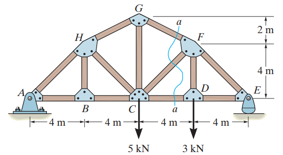
The first example is the 2D Truss shown in the figure. The figure and the problem are taken from the book "Engineering Mechanics: Statics" from Russell C. Hibbeler [1]. The problem, as described in [1] is stated as:
"Determine the force in member CF of the truss. Indicate whether the member is in tension or compression. Assume each member is pin connected."

Note that this is a statically determinate 2D Truss. In statically determinate trusses, all support reactions and member forces can be determined only by taking into account the equilibrium equations of the Model. This means that the Material Elastic Modulus (E) and the Section Area (A) properties of each member are not important in determining these quantities. Any E and A, for any member, will lead to the same results, when forces and support reactions are concerned. The same is not true for displacements. Displacements do depend on the Elastic Modulus and the Area of each member, but they are not asked for in this problem, at least in the book.
For our calculations in %PROGRAM NAME%>, we need to assign a Material and a Section to each Element, as the program is general and can analyze any 2D Truss, statically determinate or statically indeterminate, while it also calculates the displacements of all Nodes, among many others.
To draw a structure quickly without the need to set the Material and Section properties manually, EngiLab Truss.2D offers the "QuickStart" option, where the program asks the user if he/she agrees to assign a predefined Material and Section to each Element drawn on screen. The predefined Material and Section properties that EngiLab Truss.2D assigns to each member when drawn on screen are the following:
Material
The predefined Material is "Steel S 235" with the following properties:
•Elastic Modulus E = 210 GPa
•Density d = 7850 kg/m3
•Yield Stress fy = 235 MPa
Section
The predefined Section is "IPE 200" with the following properties:
•Area A = 28.5 cm2
•Moment of Inertia I = 1943 cm4
•Example 1 - Hand Calculations
•Step 1. Define the System of Units
•Step 4. Draw the Model on screen
•Step 8. Define Elemental Loads
•Step 9. Define Body (Acceleration) Loads
•Step 11. View the Analysis Results on screen
•Step 12. View the analytical results
•Analysis Validation (optional)
References
[1] Engineering Mechanics: Statics, R.C. Hibbeler, 14th Edition, Pearson Prentice Hall, ISBN-13: 978-0133918922, 2016.