About 2D Trusses
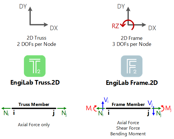
EngiLab Truss.2D specializes in the analysis of 2D Trusses. In EngiLab Truss.2D, each Node has 2 Degrees Of Freedom (DOFs), the X- and the Y- displacement. There is no rotational DOF, as all members are free to rotate at their ends, unlike in 2D frames. The figure below explains this and highlights the differences between EngiLab Truss.2D and EngiLab Frame.2D programs.

Trusses are used commonly in Steel buildings and bridges. A Truss has the following properties:
•All the members are straight and remain straight after the deformation.
•Members are connected together with pin joints.
•Members are connected only at the ends of the members.
•All external forces (loads & reactions) must be applied only at the joints.
•As a result, the members have only axial forces.
•Every member of a truss is essentially a 2 force member (see above).
•There is no shear and no bending within the Element.
Elemental (Uniform) Loads in 2D Trusses
Trusses are usually assumed to be of negligible weight (compared to the loads they carry). If self-weight of the members or other distributed loads (such as wind, snow and inertial forces) need to be taken into account, then they must be converted to equivalent Nodal Loads. In the end, for the Analysis needs, there will be only Nodal Loads on the structure. Doing this, the effects of bending on the Elements are neglected
This is the approach that EngiLab Truss.2D also uses. Self weight can be applied, as discussed in the Body (Acceleration) Loads section, yet for the analysis it is automatically converted to equivalent Nodal Loads. The same is true for Elemental (Uniform) Loads defined on any member. Uniform loads can be applied to members, but again they are automatically converted to equivalent Nodal Loads before the Analysis takes place. As a result, the Model to be analyzed has all the properties of a 2D Truss Model, discussed above.
Assuming that a 2D Truss member carries a uniform load w (for example, in kN/m units), the total load is F=w*L (in kN), where L (in m, in this example) is the Length of the Element. For the Analysis, each Node (start and end Node) of this members takes a Force equal to F/2=w*L/2. This is shown schematically below.
