After you have defined the Material and the Sections, you can start drawing your Model on screen, as follows:
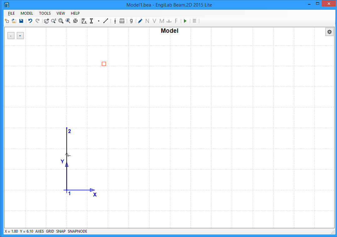
•First make sure that SNAP and SNAPNODE are both activated (see bottom right of Picture below).
•If SNAP is activated (Default=True), then you can only draw Nodes and Elements at increments defined by the Snap Size setting (Default=0.1). This is fine for our example.
•If SNAPNODE is activated (Default=True), then you can "catch" Nodes so that new elements can be connected to existing Nodes. This is essential for building our Model.
•Left-click on screen, hold down the left button and then release it at another location to define a new Element and two nodes at ends i, j.
•Note: All Elements that are defined on screen are assigned Material 1 and Section 1. We will correct this later on.
You can start at any point. Let's start from point 0,0 (Origin of axes). Draw the first column as shown below. Release the left button after you have done a distance of 3 in the Y Direction.
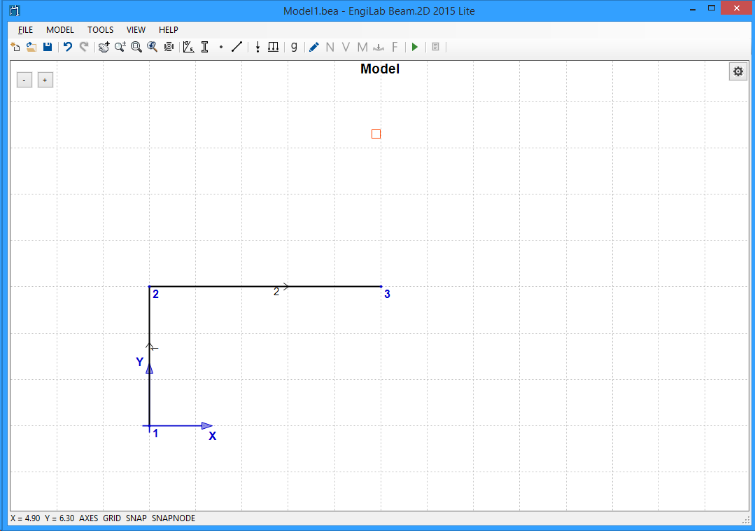
Continue with the Beam. Hold down the left button starting at Node 2 and release it at distance 5 in the X Direction. The picture should be as follows.
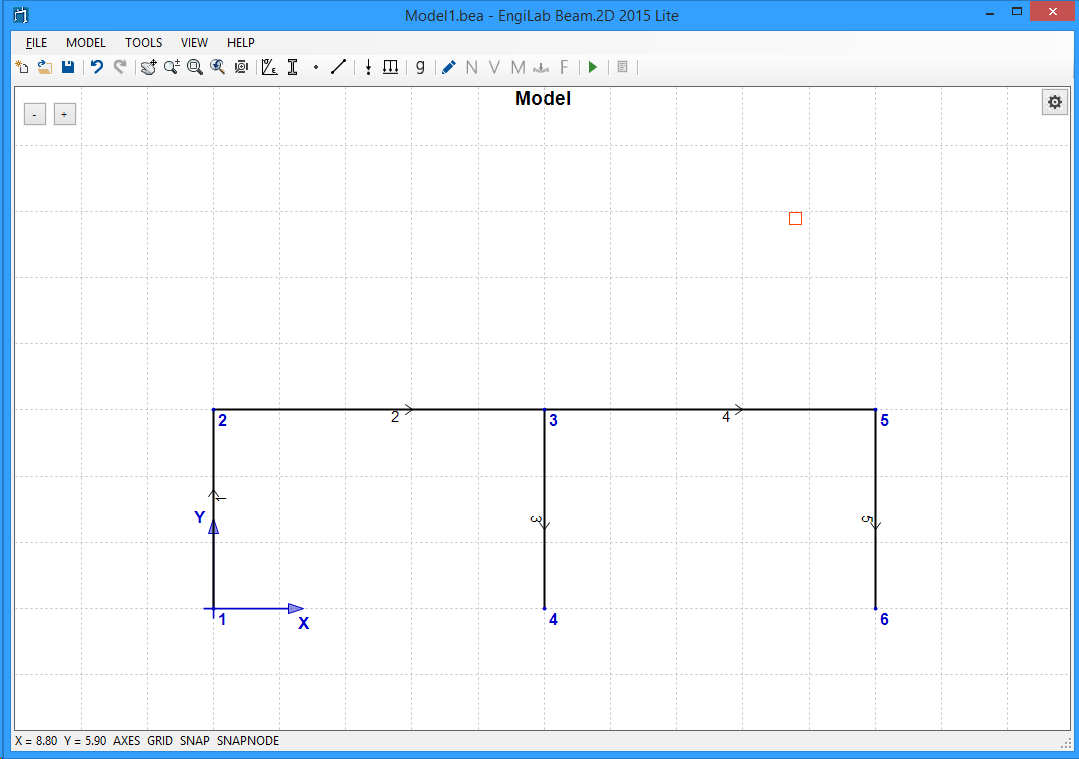
Using the same technique, continue with the other Columns and Beams of the first story. The picture should be as follows.
Continue with the Columns and Beams of the second story. Finally the picture should look as follows.
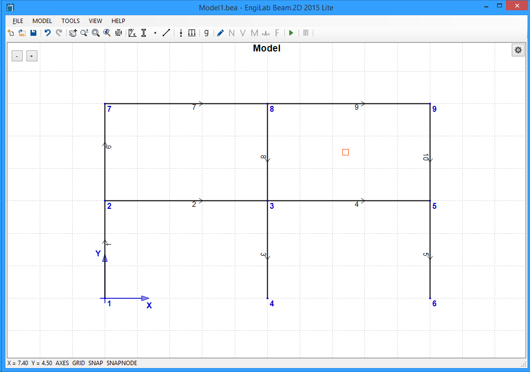
That's it! Now you have built the basic Model. But you need to apply some corrections. For example, now all Elements are assigned Section 1 (Columns), but the horizontal members have to be corrected as they must be assigned Section 2 (Beams). Also, loads (Nodal and Elemental) and also supports have to be added to the Model.