Now let's see the Elements. In our example, the Elements have the correct Material and Section, but we need to do two modifications:
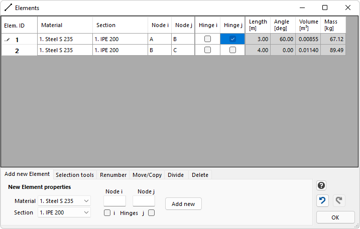
•We need to add the internal hinge at Node B. Internal hinges are added in the Element properties. In this example, it has to be added either at the end of Element 1 or at the beginning of Element 2.
•There is a Nodal Load acting along Element 2 (in the middle of it). Since in EngiLab Frame.2D point loads must always be defined as Nodal Loads, this means that a Node is needed in the middle of Element 2. Element 2 has to be split in two equivalent Elements.
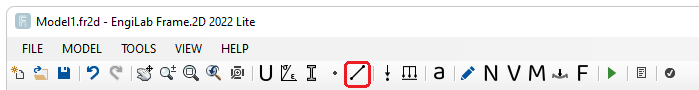
Click ![]() to edit Elements. For details, see Elements.
to edit Elements. For details, see Elements.
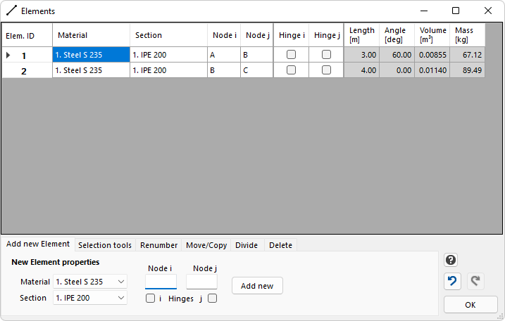
We see the two Elements and their properties. We see that the lengths of the two Elements are 3.00 m and 4.00 m, which is correct. Also, the Angle of Element 1 is 60 deg, which is also correct. We define a hinge at the end j of Element 1 as follows:
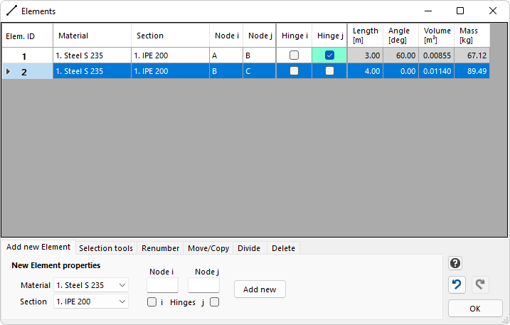
Next we need to divide Element 2 into two Elements. For this we click the "2" of Element 2 and we highlight the entire second row as follows:
We click the Divide tab.
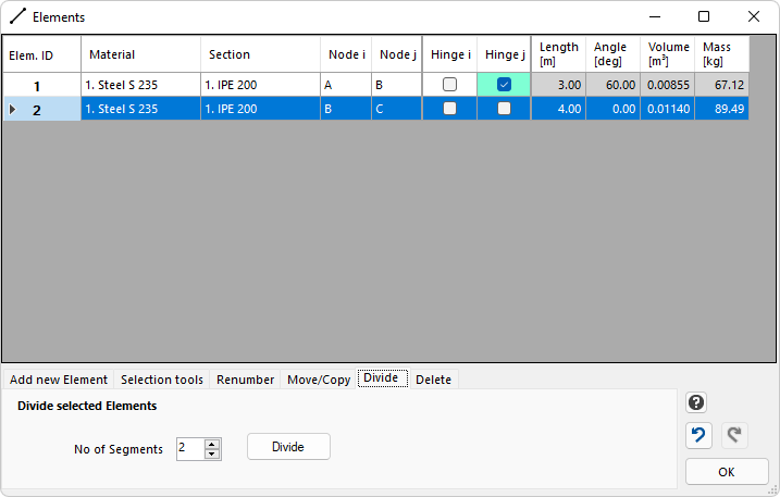
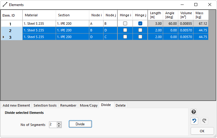
The default Number of Segments is 2 and we can keep it. Having selected Row (Element) 2, we click the "Divide" button. Then we get a new Element. Now Element 2 is 2 m and also Element 3 is 2 m long. The previous Element has been divided into 2 equivalent Elements.
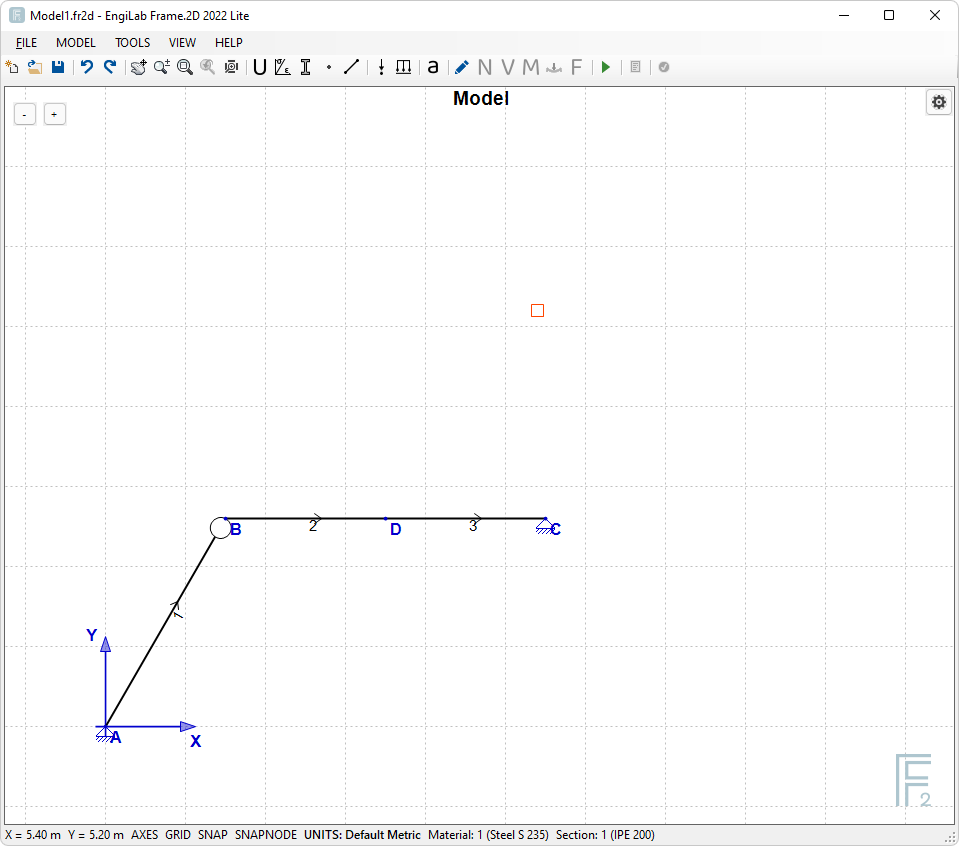
See now our Model. A new Node has been generated in the middle of the previous Element. We can now define our Nodal Load on this new Node D.
Then Click OK to exit Elements.