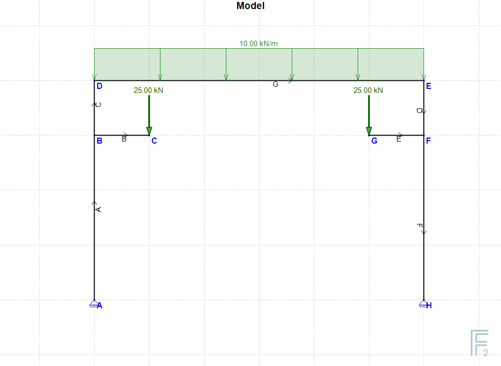
EngiLab Frame.2D uses the Finite Element Method (FEM) to analyze the Model. According to FEM, displacements are computed only for Nodes. Loads within elements (elemental loads) are distributed to the connecting Nodes and the analysis results give the Node Displacements vector (displacements at the positions of the Nodes). Calculating the intermediate displacements within elements and drawing accurately the deformed shape of the model is not an easy task, especially for cases of Elements with Hinges and linear varying loads on. EngiLab Frame.2D uses special computational techniques that give 100% accurate results without any approximations, for the displacements (and forces) along an element.
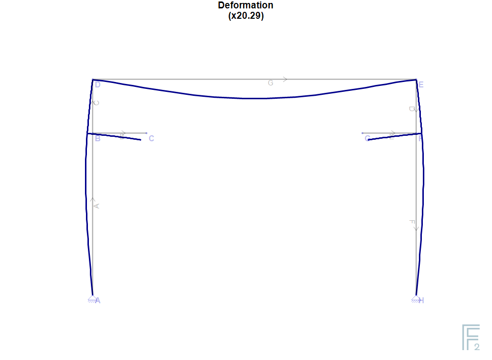
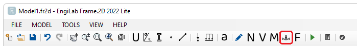
After setting up the model and analyzing it (Clicking the 'Analyze' button ![]() ) you can click
) you can click ![]() to see the deformed shape of the Model.
to see the deformed shape of the Model.
•![]() : Deformation
: Deformation
Note: Deformation values are given also on screen, if the mouse pointer hovers over an element. The values that are given on screen are the dX, dY, dx and dy displacements of the corresponding point of each element.
•dX and dY are the X- and Y- displacements of a point, respectively, in Global axes. For example a positive dX means displacement to the right, while a positive dY means displacement upwards.
•dx and dy are the x- and y- displacements of a point, respectively, in Local Element Axes, where x is defined from the Start Node i and the End Node j of the Element and y is perpendicular to it.
See the illustrative example below which explains this convention.
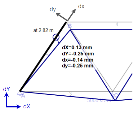
Example