Nodes connect Elements. Each Element has a Start Node (i) and an End Node (j). Each node is located at a (X, Y) Point (Global Axes) in the 2D plane and it has 3 Degrees Of Freedom (DOFs):
•![]() X-Displacement
X-Displacement
•![]() Y-Displacement
Y-Displacement
•![]() Z-Rotation
Z-Rotation
Each DOF can be:
•Free to move (No support, No spring)
•Fixed (Fully constrained, not able to move at all)
•With a spring on (Given the spring stiffness, the spring provides a reaction force that is proportional to the displacement of the corresponding DOF).
Note that a DOF with a spring on is at an intermediate state between Free and Fixed. If the spring stiffness is zero, then it will behave exactly as a free DOF, while if the spring stiffness reaches infinity, it will behave as a fixed DOF. Any value in between zero and infinity will provide some stiffness.
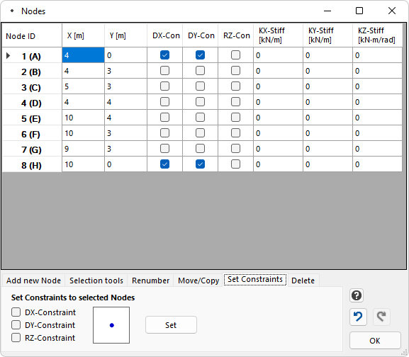
Node properties
The Node properties are the following:
•Coordinates: X, Y
•Constraints: DX-Con, DY-Con, RZ-Con. Each one can be Checked or Not checked.
•Springs stiffness: DX-Stiff, DY-Stiff, RZ-Stiff. Each stiffness component has a real positive value, or a zero value. The stiffness cannot have a negative value.
Coordinates
Each node is located at a (X, Y) Point (Global Axes) in the 2D plane.
Constraints
The properties DX-Con, DY-Con, RZ-Con determine whether the corresponding DOF (DX, DY or RZ) of the Node is constrained or not. DX and DY are the X and Y displacements of the node, respectively. RZ is the rotation around the Z axis.
Each DOF can be:
•Free (0 = Unchecked), or
•Fully constrained (1 = Checked).
As a result, there are in total 8 types of Nodes, as follows:
Picture |
DX-Constraint |
DY-Constraint |
RZ-Constraint |
Description |
|
NO |
NO |
NO |
Free Node (000) |
|
|
NO |
NO |
y-Roller (100) |
|
NO |
|
NO |
x-Roller (010) |
|
|
|
NO |
Pinned (110) |
|
|
|
|
Fixed (111) |
|
NO |
NO |
|
(001) |
|
|
NO |
|
(101) |
|
NO |
|
|
(011) |


Springs
The properties DX-Stiff, DY-Stiff, RZ-Stiff determine the Stiffness of the Spring (Elastic constant) of the corresponding DOF. A spring provides a spring reaction force that is proportional to the displacement of the corresponding DOF. Each stiffness component has a real positive value, or a zero value. The stiffness cannot have a negative value.
Note: A DOF that has a spring should not be constrained, as there is no point in that - Any constrained DOF will not have a displacement and as a result the spring reaction will be zero. In any case, if for a given DOF there is a spring and it is also constrained, then the spring is ignored and the DOF is handled as fully constrained.
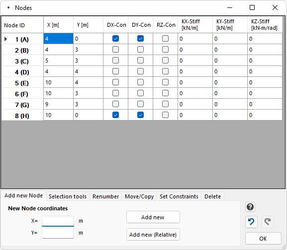
Add new Node
To add a new Node, you can type the X and Y Coordinates of the Node and click the "Add new" button. This uses the absolute coordinates X, Y for the definition of the new Node.
Another convenient way to define a new Node is by using relative coordinates, based on the coordinates of a previously selected Node. For example, you select Node (row) 10, you set the X and Y values, and then you click "Add new (Relative)". The new Node is defined in relation to the previously selected Node. This is very convenient when defining Nodes with a fixed distance between them. In this case, the previous Node acts as the selected Node, so you can keep adding Nodes using relative coordinates based on the previously defined Node.
Note: If multiple Nodes are selected and the "Add new (Relative)" button is clicked, then the Node with the highest ID (of the selected ones) is taken into account as the reference Node for the definition of the new Node.
Edit an existing Node
You can click on the table and you can easily edit the properties of an already existing Node. Any change you make is automatically reflected to the Model on the screen.
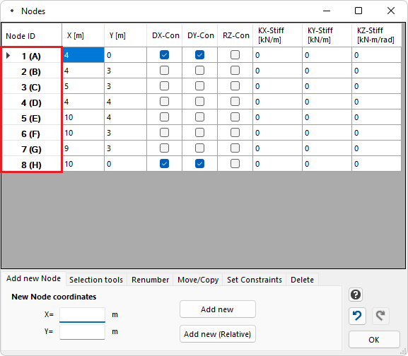
Select existing Node(s)
You can click on a row number to select one or more Nodes. Then you can apply actions to the selected Nodes (renumber, move/copy, set constraints, delete, etc).
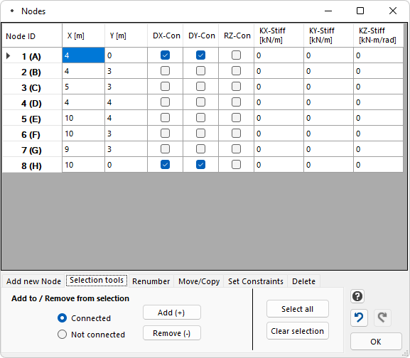
Selection tools
This tab provides tools for the selection of Nodes. For example, you can select (add to selection) or deselect (remove from selection) all the Nodes that are connected to Elements, or all the Nodes that are NOT connected to Elements. This is useful when for example you need to Delete all the Nodes of the Model that are not connected to Elements. You can also Select all Nodes, or Clear the selection.
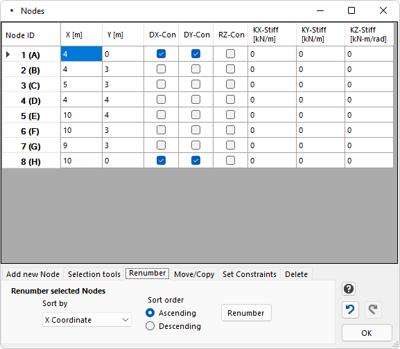
Renumber Nodes
In order to perform this action, first you have to select the entire row(s) of the corresponding Node(s) and then apply the action.
A tool is available for the renumbering of (the selected) Nodes, based on various criteria:
•X Coordinate
•Y Coordinate
•(X + Y)
•(X - Y)
•(X² + Y²)
First, the Nodes have to be selected. Then we select the "Sort by" field and then the sort order (ascending or descending). Finally, we click the "Renumber" button.
Important: Renumbering is done for the selected Nodes. The non-selected Nodes remain unchanged. To renumber all Nodes, all Nodes have to be selected first.
Move/Copy Nodes
In order to perform these actions, first you have to select the entire row(s) of the corresponding Node(s) and then apply the action.
This tool is used for moving or copying Nodes. The user specifies the Move/Copy Vector {V}={dX, dY}.
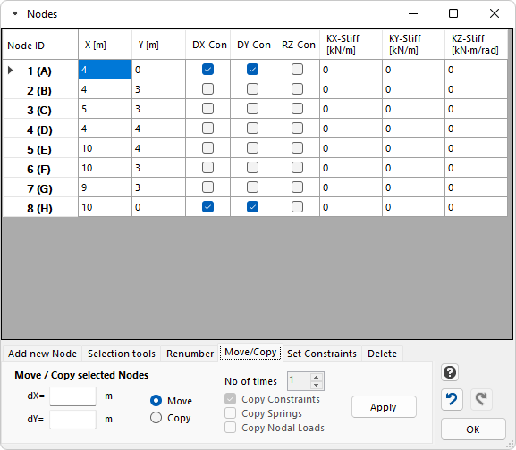
Move Nodes
•Multiple Nodes (one or more) can be selected to be moved at once.
•Move Nodes can only be applied once (only one time), not a number of times (only copy works with the option to apply it over a number of times).
•With the Move command, several nodes can be moved to a new location. The user defines the move vector as {dX, dY}.
•Nodes are moved together with their supports, springs and any nodal loads on them.
•If another Node is already at the new position, it is not affected. In the end there will be two Nodes with different IDs, at the same position.
•If elements are connected to the Nodes that move, they will be moved also together with the Nodes, as Elements depend on their Nodes for their start and end points.
•If both Nodes (start Node i and end Node j) of an Element move, then the Element itself is moved without any change in its length or its other properties. The Element simply has a new position in the 2D plane, as both its Nodes move the same.
•If only one Node (either the start Node i or the end Node j) of an Element moves, then the Element’s length will change. An Elemental load on the Element will not change its value (as it is defined per unit length of the element), but the total load (total force) on the element will do change, due to the change in the length of the Element.
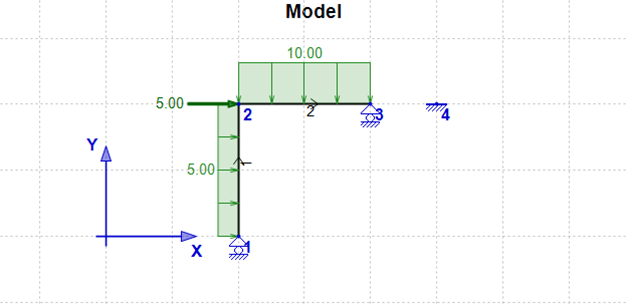
Example 1 – Moving Nodes

In the above example, Nodes 2 and 3 are moved with the vector {DX=1, DY=0}. The result of the operation is the following:
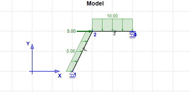
•Note the change in the length of Element 1 because of Node 2 moving to point (3, 2) from point (2, 2).
•The length of Element 2 is not affected as both its Nodes (start and end) have moved the same.
•The uniform load on Element 1 remains 5 units of force per unit of length, but the total load on Element 1 has now changed to 5*2.24= 11.2 from 5*2=10 as it refers to the new length of the element, which is now increased.
•Node 3 has moved to (5, 2) where Node 4 was already previously. Node 4 is not affected and in the end, there will be two Nodes at the same location (5, 2).
Copy Nodes
•Multiple Nodes (one or more) can be selected to be copied at once.
•Copy Nodes can be applied multiple times (up to 50) with a single click.
•With the Copy command, several Nodes can be copied to a new location. The user defines the copy vector as {dX, dY} and the number of times the operation will be applied.
•If the corresponding check boxes are checked, Nodes are copied together with their Constraints (supports), Springs and Nodal Loads (forces or moments)
•By default, the "Copy Constraints" and the "Copy Springs" check boxes are checked, while the "Copy Nodal Loads" check box is NOT checked. All these can be changed by the user.
•If another Node is already at the new position, it is not affected. In the end there will be two Nodes with different IDs, at the same position.
•Copy Nodes does not affect any Elements, as elements depend on existing Nodes only.
Example 2 – Copying Nodes
Copy Nodes works similarly with Move Nodes, but this time new Nodes are created instead of moving already existing ones. In the previous model of Example 1:
We now copy Nodes 1, 2 and 3 with the vector {DX=3, DY=0}, 2 times. The result of the operation is the following:
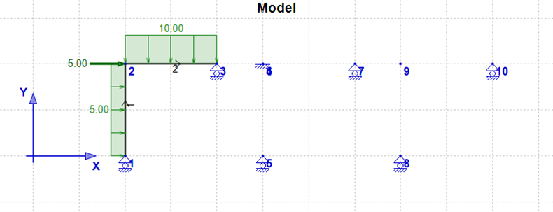
•Node 4 was already at (5, 2) and is not affected. New Node 6 is also created at the same location (5, 2).
•Constraints (and springs) are copied together with the Nodes.
•Nodal forces (or moments) are NOT copied together with the Nodes (see Node 2 and new Nodes 6 and 9).
•Copy Nodes does not affect any Elements as elements depend on existing Nodes only.
Set Constraints
In order to perform this action, first you have to select the entire row(s) of the corresponding Node(s) and then apply the action.
This tool is used for setting constraints on selected Nodes. You can set constraints for more than one Nodes at a time. First select the Nodes (rows) that you want to set the constraints on. Set the constraints by checking the DX, DY or RZ constraint checkbox. Finally, click the "Set" button to perform the operation.
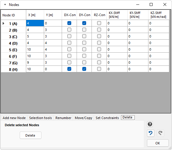
Delete Nodes
In order to perform this action, first you have to select the entire row(s) of the corresponding Node(s) and then apply the action.
This tool is used for deleting Nodes. You can Delete more than one Nodes at a time. First select the Nodes (rows) that you want to delete. Then, click the "Delete" button to delete the Nodes.