After you have defined the Material and the Section, you can start drawing your Model on the screen.
•First make sure that SNAP and SNAPNODE are both activated (see bottom left of Picture below).
•If SNAP is activated (Default=True), then you can only draw Nodes and Elements at increments defined by the Snap Size setting (Default=0.1). This is fine for our example.
•If SNAPNODE is activated (Default=True), then you can "catch" Nodes so that new elements can be connected to existing Nodes. This is essential for building our Model.
•Left-click on screen, hold down the left button and then release it at another location to define a new Element and two Nodes at ends i, j.
•Note: All Elements that are defined on screen are assigned the Default Material and the Default Section. If there is only one Material or Section, then this is the Default Material or Section, otherwise the user can select among the different Materials or Sections.
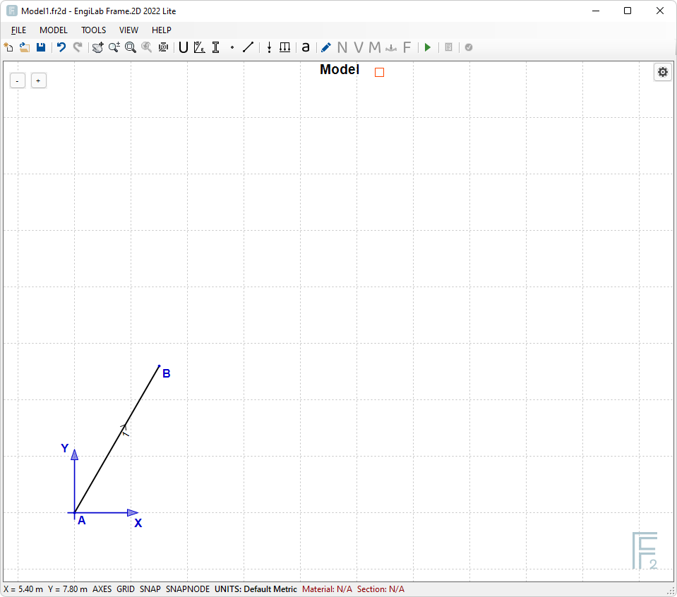
You can start at any point. Let's start from point 0,0 (Origin of axes). Draw the first member as shown below. Starting from point (0, 0), release the left button after you have reached the (1.5, 2.6) point on screen. Note that the Coordinates of Node B are:
X=3*cos(60°) = 1.5 m
Y=3*sin(60°) = 2.598076211 m
Later on we will correct the Y value, giving the exact 2.598076211 m in Nodes Coordinates.
Coordinates are shown on the status bar at the bottom left corner of the window.
A. In case you have defined the Material and the Section manually (you have followed Steps 3 and 4), you will get the following screen:
B. In case you have NOT defined the Material and the Section manually (you have skipped Steps 3 and 4), you will get the following prompt:
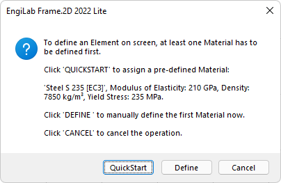
Click QuickStart to quickly assign the predefined Material. You get another prompt:
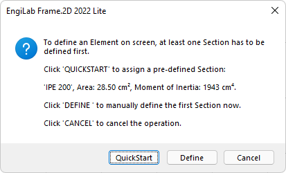
Click QuickStart again to quickly assign the predefined Section and start drawing.
In both cases, you will finally get the first Element and the first two Nodes as follows:
Using the same technique, continue with the other horizontal Element, moving with relative coordinates as @{4, 0} from Node B, as shown in the figure below.
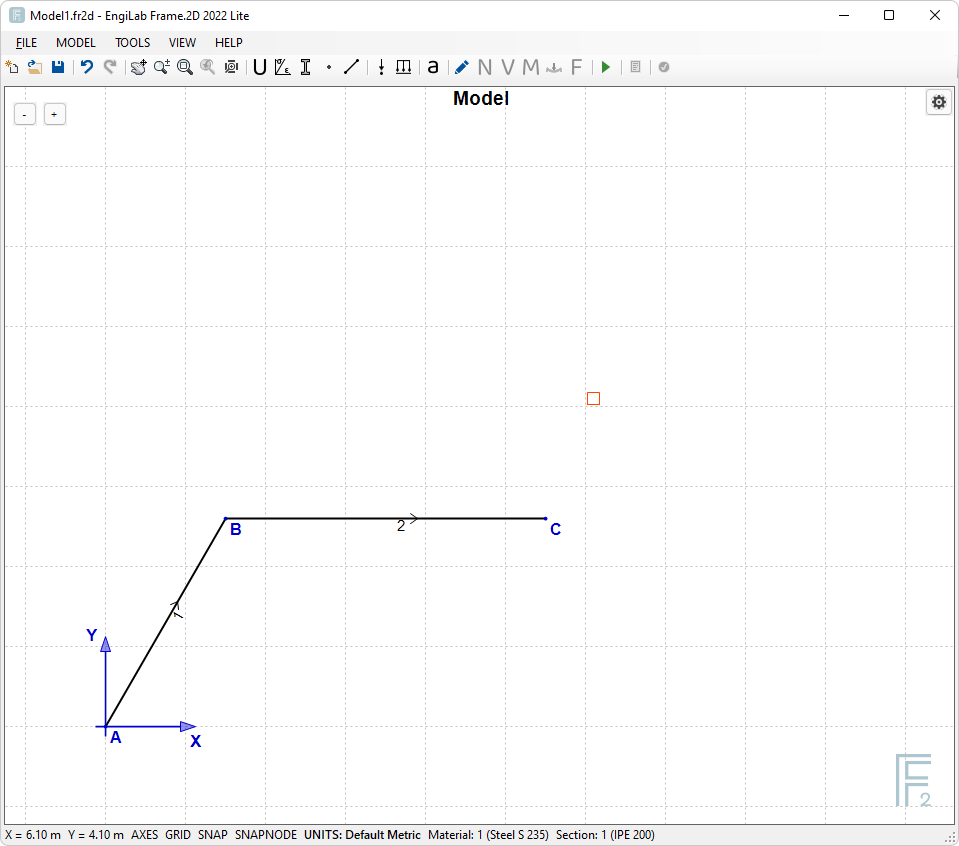
Now we have defined Nodes A, B, C and Elements 1 and 2. Note that Nodes B and C are NOT yet in their correct locations. We will fix this in the next step! Then we will apply the Supports and the external loading.