The hinges (rotational releases) of a model is an issue which requires our attention. There are two kinds of hinges: External hinges (Pinned constraints) and Internal hinges.
External hinges (Pinned constraints)
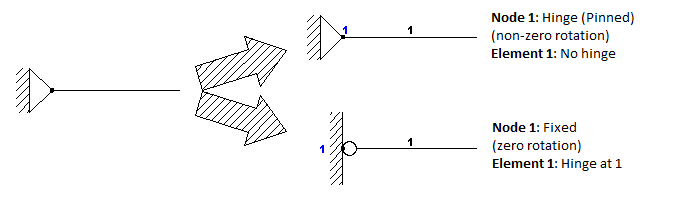
1. An external hinge to which only ONE element is connected can be given in a model using two possible ways (the result of the analysis should be the same):
•A. As a pinned Node (Node 1 - "110") connecting an Element with no hinge at end 1
•B. As a fixed Node (Node 1 - "111") connecting an Element with a hinge at end 1.
Note that only by using the first option (A) you can get the rotation of the Element at end 1 in the analysis results.
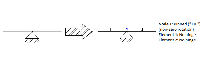
2. An external hinge to which more than one elements are connected must be given in the Model as follows:
Internal hinges
An internal hinge must be given always as a hinge of one or more elements as follows:
1. 'Partial' internal hinge (Applies to some of the connecting elements)
2. 'Full' internal hinge (Applies to all connecting elements)
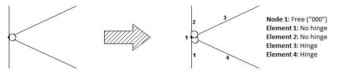
A 'full' internal hinge which applies to all connecting elements means that for each of the connecting elements the bending moment value at the specific element end is zero. To model that case, you need as many as ('connecting elements' - 1) hinges for the connecting elements. Only one of the connecting elements should have no hinge at the specific end, no matter which of them.
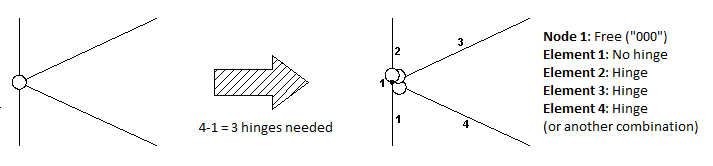
Note: In the case of a 'Full' internal hinge, each connecting element has its own rotation at the hinge end. The program only calculates the rotation of the element with no hinge. In the example below, the rotation of element 1 at end 1 will be calculated, while the rotations of the elements 2, 3 and 4 at end 1 will not be given in the analysis results. By using different combinations of releases, one can get the rotations of any connecting element separately.